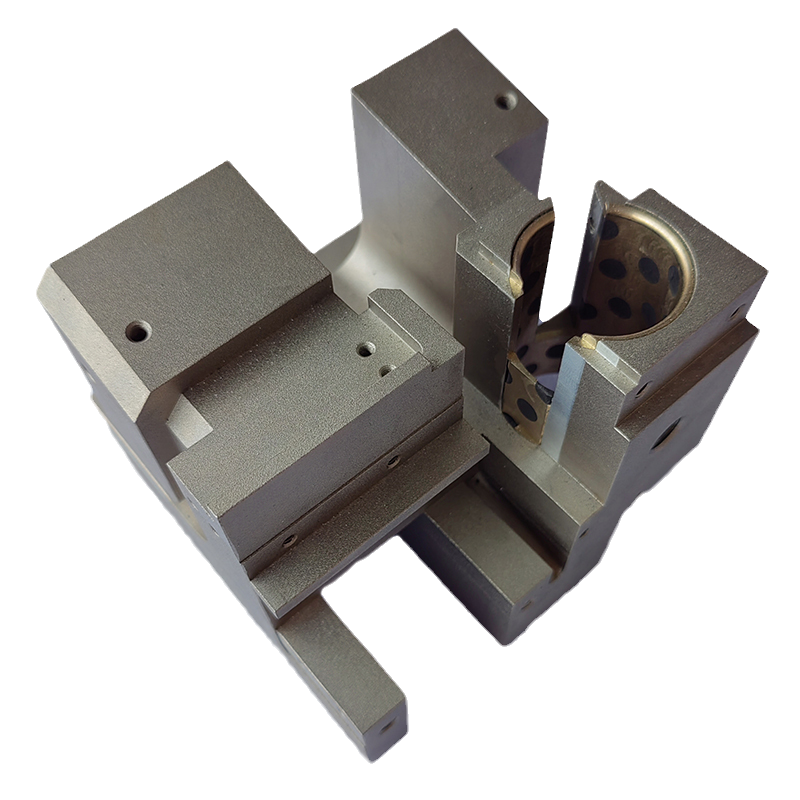
General rules for precision mold design:
1. Use the FUTABA standard mold base structure to form the mold base.
2. Use positive steel or standard mold parts and accessories of the same specification.
3. All guide pins (GUIDE PIN) and bushings (BUSHING) must have a convex shape at the end.
4. The paper size of all mold design drawings shall be uniformly used in the full-open size, and the production shall be started after approval.
5. When processing the finished part of the mold, the half value of the dimensional tolerance of the finished drawing should be used as the processing tolerance, and the tolerance of the finished drawing should not be used for processing.
6. All units of measurement are based on the imperial system, the length is in millimeters, the weight is in kilograms, and the temperature is in Celsius (C).
7. The pressure is in English PSI, 1PSI=1 pound/square inch = 14.2 kg/square centimeter.
8. Confirm the die thickness, clamping die stroke and ejection stroke.
9. The positions of the four sides of the male and female molds have at least one hanging mold hole on each adjacent side of the "A" and "B" plates, and at least one side of the other templates has a hanging mold hole.
10. Any one of the four guide pins must be eccentric, that is, not symmetrical with the other three, so as to prevent the male and female molds from being closed in reverse.
11. Print the steel specifications and hardness on the bottom surface of the mold core.
12. List the material table in detail and indicate the material and surface treatment specifications, and indicate the wattage specification and voltage of the electric heater.
13. Print, number all mold parts.
14. Both sides of the mold should be fixed with iron bars before packing to prevent the mold surface from being separated.
15. When there is more than one cavity in the same finished product, continuous numbers should be used to identify the cavity.
16. There should be a hole in the mold base at the center of gravity of the mold to avoid the mold from tilting when the mold is lifted, and make sure that the thread and depth are sufficient to load the mold.
17. Parting LINE LOCKS should be installed unless the mold core has a large area of stepped breakage.
18. When the depth of the rib exceeds 5mm, it is necessary to add an escape pin at the bottom of the rib or use an insert to facilitate plastic filling.
19. When the pin is used as a plane break, the top of the pin should be extended into the steel to avoid pressure damage or deformation of the top surface of the pin.
20. The size of the important part of the finished product should be slightly reserved to avoid repair welding due to excessive processing size.
21. The mold core is not allowed to repair welding without permission.
22. When repairing the mold with repair welding under special circumstances, the same material of the mold should be used as the welding rod, so as to avoid the different materials affecting the appearance of the finished product and leaving traces.

 24-hour service hotline:
 24-hour service hotline:


